Introduction
When engineers and procurement teams evaluate heat exchanger design options, one question comes up consistently: shell and tube or plate heat exchanger?
Both are widely used across oil & gas, chemical processing, power generation, and water treatment industries – but they serve very different operational demands. The right choice depends on pressure ratings, fluid types, temperature range, maintenance access, and budget.
This guide provides a detailed engineering comparison of shell & tube heat exchangers (S&T HX) and plate heat exchangers (PHE), covering design principles, performance characteristics, code compliance, and ideal application scenarios.
What Is a Shell & Tube Heat Exchanger?
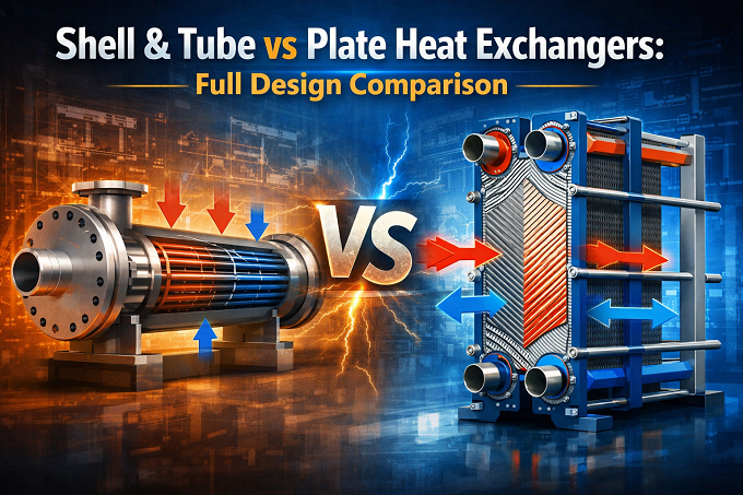
A shell & tube heat exchanger consists of a bundle of tubes enclosed within a cylindrical shell. One fluid flows through the tubes (tube-side) while another flows over the tubes within the shell (shell-side), allowing heat transfer between the two streams without mixing.
Key Design Features
- Designed to TEMA standards (R, C, or B class) and ASME Section VIII
- Handles high-pressure and high-temperature applications – up to 300+ bar and 600°C
- Available in fixed tubesheet, U-tube, and floating head configurations
- Suitable for two-phase flow, steam condensers, and reboilers
- Robust performance with viscous, abrasive, or fouling-prone fluids
Shell & tube designs are the industry standard in refineries, offshore platforms, and power plants where extreme conditions are routine.
What Is a Plate Heat Exchanger?
A plate heat exchanger uses a series of thin, corrugated metal plates to transfer heat between two fluids. The plates are stacked and sealed with gaskets (gasketed PHE) or brazed/welded together, creating alternating hot and cold flow channels.
Key Design Features
- Compact footprint – up to 5x smaller than an equivalent shell & tube unit
- High heat transfer coefficients due to turbulent flow in narrow channels
- Operating limits typically up to 25–30 bar and 200°C (gasketed type)
- Compliant with ASME, EN 13445, and TEMA for applicable configurations
- Easy to expand capacity by adding plates – modular design
Plate heat exchangers are preferred in HVAC, food processing, pharmaceutical plants, and district cooling applications where space is limited and fluids are relatively clean.
Shell & Tube vs Plate Heat Exchanger: Design Comparison Table
Parameter | Shell & Tube HX | Plate HX | Ideal Use Case |
Pressure Rating | Up to 300+ bar | Up to 25–30 bar | High-pressure: S&T |
Temperature Range | Up to 600°C+ | Up to 200°C | Extreme temps: S&T |
Heat Transfer Efficiency | Moderate | High (turbulent flow) | Compact duty: PHE |
Fouling Resistance | Better (larger tubes) | Lower (narrow gap) | Dirty fluids: S&T |
Maintenance | Moderate (tube cleaning) | Easy (gasketed plates) | Easy access: PHE |
Footprint | Large | Compact | Space-limited: PHE |
Capital Cost | Higher | Lower to moderate | Budget-sensitive: PHE |
TEMA / ASME Compliance | TEMA, ASME Sec VIII | ASME, EN 13445 | Coded design: S&T |
When to Choose Shell & Tube
Shell & tube heat exchangers are the right choice when:
- Operating pressures exceed 30 bar or temperatures exceed 200°C
- Fluid contains suspended solids, scaling agents, or is highly viscous
- The application involves phase change – condensing or evaporating
- TEMA class compliance or ASME Section VIII certification is required
- Long-term reliability in harsh offshore or refinery environments is critical
When to Choose a Plate Heat Exchanger
Plate heat exchangers are the better option when:
- Compact installation space is a primary constraint
- The application involves clean, low-viscosity fluids at moderate pressures
- High thermal efficiency is needed at lower capital cost
- Future capacity expansion is anticipated (gasketed PHE allows plate addition)
- Ease of maintenance and cleaning is a priority
Role of FEA and CFD in Heat Exchanger Design
Whether you select a shell & tube or plate heat exchanger, advanced simulation tools are critical for ensuring thermal and structural performance before fabrication.
Finite Element Analysis (FEA): Validates nozzle loads, thermal stresses, tube-to-tubesheet joints, and pressure boundary integrity under ASME Sec VIII requirements.
CFD Simulation: Models fluid flow distribution across tube bundles or plate channels, identifies hotspots, optimises baffle spacing, and ensures uniform heat transfer efficiency.
At Neocent Engineering, we integrate FEA and CFD into every heat exchanger design project to eliminate costly rework and meet global code requirements from day one.
Conclusion: Making the Right Choice
There is no single winner in the shell & tube vs plate heat exchanger debate – the right choice is application-specific.
Choose a shell & tube heat exchanger for high-pressure, high-temperature, and fouling-heavy services where code compliance and long-term durability matter most. Choose a plate heat exchanger for clean, moderate-duty services where compactness, efficiency, and ease of maintenance are priorities.
Partnering with an experienced heat exchanger design consultancy ensures your selection is backed by rigorous thermal analysis, FEA validation, and full code compliance – reducing risk and lifecycle cost.
Need Expert Heat Exchanger Design Support?
Neocent Engineering provides complete heat exchanger design consulting services – including shell & tube and plate heat exchanger design, TEMA/ASME compliance, FEA, and CFD analysis. Contact us at sales@neocentengineering.com or call +91 8000 860 806.
FAQs
Q1: What is the difference between shell & tube and plate heat exchangers?
Shell & tube handles high pressure (300+ bar) and extreme temperatures using a tube bundle inside a shell. Plate heat exchangers use stacked metal plates, offering a compact size and better thermal efficiency but limited to moderate pressures and temperatures. Choose shell & tube for heavy industry; plate for clean, space-limited applications.
Q2: Which heat exchanger is best for oil & gas?
Shell & tube heat exchangers are the standard choice for oil & gas. They meet TEMA and ASME Section VIII requirements, withstand extreme conditions, and handle fouling-prone or two-phase fluids found in refineries and offshore plants.
Q3: What is the TEMA standard in heat exchanger design?
TEMA (Tubular Exchanger Manufacturers Association) defines design, material, and fabrication rules for shell & tube heat exchangers. It has three classes – R (severe), C (commercial), and B (chemical) – ensuring safety and reliability across industrial applications.
Q4: How does CFD help in heat exchanger design?
CFD simulates fluid flow and heat transfer before fabrication. It detects pressure drops, hotspots, and flow imbalances – allowing engineers to optimise baffle spacing and nozzle layout, reducing costly design revisions.
Q5: When is FEA required for heat exchanger design?
FEA is needed when standard ASME calculations are insufficient – such as complex nozzle loads, thermal expansion, cyclic loading, or non-standard geometries. It provides simulation-backed validation required for third-party and code compliance reviews.

Krupal Patel
Krupal Patel is the CEO of Neocent Engineering Pvt. Ltd., Ahmedabad, specializing in advanced engineering solutions. With over 8 years of expertise in Product Design, FEA, CFD, and ASME-BPVC stress analysis, he has successfully delivered high-precision projects across pressure vessels, piping, and structural systems.