
Introduction
Finite Element Analysis (FEA) is widely used to evaluate structural strength, deformation, stress distribution, and component performance under different loading conditions. However, even a technically correct simulation model can produce unreliable results if its boundary conditions are incorrectly defined.
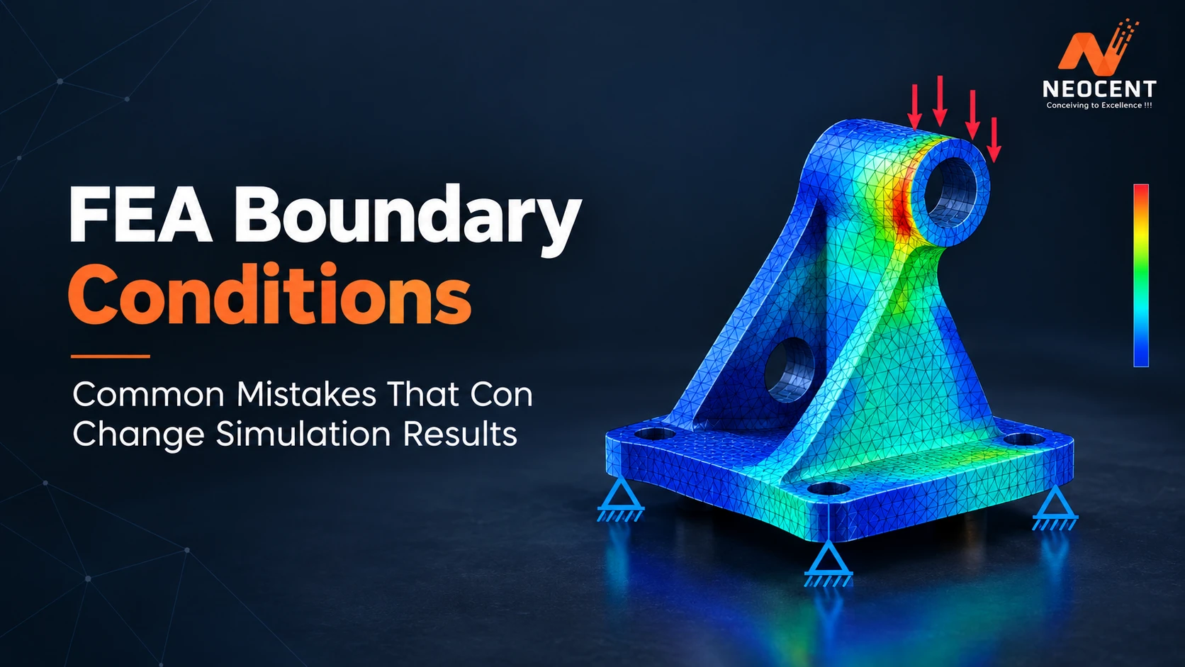
Boundary conditions determine how a component is supported, constrained, or exposed to external loads during simulation. Incorrect constraints can create unrealistic stiffness, excessive stress concentrations, or misleading deformation patterns, potentially affecting engineering decisions and product safety.
Understanding common boundary condition errors is essential for engineers working on mechanical components, pressure vessels, structural assemblies, and industrial equipment. This guide explains the major mistakes, their impact on simulation accuracy, and practical methods to avoid them.
What Are Boundary Conditions in FEA?
Boundary conditions in Finite Element Analysis define how a model interacts with its surrounding environment. They specify the constraints, applied forces, displacements, temperatures, or other physical conditions acting on a component.
In simple terms, boundary conditions tell the simulation software what a component can move, how it is supported, and what external influences it experiences.
Common types include:
- Displacement constraints: Restrict movement in selected directions.
- Fixed supports: Prevent translation and rotation at specified locations.
- Force and pressure loads: Represent external mechanical loading.
- Symmetry conditions: Reduce model size by representing symmetric behavior.
- Thermal boundary conditions: Define temperature, heat flux, or convection.
- Contact conditions: Represent interactions between connected or touching components.
Accurate boundary conditions are essential because FEA results depend on how closely the mathematical model represents real operating conditions.
Why Are Boundary Conditions Important in FEA?
Boundary conditions directly influence the stiffness, load transfer, stress distribution, and deformation of a simulated structure.
For example, fixing every surface of a component may prevent realistic movement and produce artificially low displacement. Conversely, insufficient constraints can allow rigid-body motion, causing solver errors or unrealistic results.
Incorrect boundary conditions may lead to:
- Inaccurate stress and displacement predictions
- Artificial stress concentrations
- Incorrect load transfer between components
- Unrealistic reaction forces
- Solver convergence problems
- Incorrect conclusions about structural safety
For engineering applications, boundary conditions should represent actual installation, support, loading, and operating conditions as closely as possible.
8 Common FEA Boundary Condition Mistakes
-
Over-Constraining the Model
Over-constraint occurs when excessive degrees of freedom are restricted, making a component behave more rigidly than it would in reality.
For example, fixing an entire mounting surface when the actual component is attached using bolts may prevent natural deformation and load redistribution.
Impact: Artificial stiffness, inaccurate stress distribution, and underestimated deformation.
How to avoid it: Model realistic support conditions, bolt connections, and permitted movements. Apply constraints only where physically justified.
-
Under-Constraining the Structure
Under-constraint occurs when insufficient restrictions are applied to prevent unwanted rigid-body movement.
A component may translate or rotate freely, even though the real assembly is supported by surrounding structures.
Impact: Solver instability, singular stiffness matrices, and unrealistic displacement results.
How to avoid it: Identify the component’s physical support arrangement and restrain the necessary rigid-body degrees of freedom without unnecessarily restricting deformation.
-
Applying Loads at Incorrect Locations
Applying forces or pressures to the wrong surfaces can significantly change the simulated load path.
For example, applying a concentrated force at a single node instead of distributing it over a realistic contact area may create a localized numerical stress concentration.
Impact: Incorrect peak stress, unrealistic deformation, and misleading structural conclusions.
How to avoid it: Apply loads over physically appropriate regions and use remote loads, distributed forces, or contact definitions when they better represent actual loading.
-
Ignoring Contact Conditions Between Components
Mechanical assemblies often contain bolted joints, flanges, supports, and connected parts. Assuming that all contacting surfaces are perfectly bonded can misrepresent their actual behavior.
For example, a bolted assembly may experience separation, sliding, or localized contact pressure under operating loads.
Impact: Incorrect load transfer, unrealistic joint stiffness, and inaccurate local stress results.
How to avoid it: Select suitable bonded, frictional, or frictionless contact definitions based on the actual connection and analysis objectives.
-
Using Incorrect Symmetry Boundary Conditions
Symmetry conditions reduce computational effort by allowing engineers to analyze only a portion of a symmetric structure.
However, symmetry is valid only when the geometry, material properties, loading, and relevant response are symmetric.
Impact: Artificial deformation restrictions and incorrect stress distribution.
How to avoid it: Verify symmetry across the complete physical problem before applying symmetry constraints. Avoid using symmetry for asymmetric loading or response conditions.
-
Neglecting Thermal Expansion
Components exposed to temperature changes expand or contract. Restricting this movement incorrectly can create unrealistic thermal stresses.
For example, a piping system connected to equipment may require flexibility to accommodate thermal expansion.
Impact: Overestimated thermal stress, incorrect reaction loads, and misleading assessment of component performance.
How to avoid it: Include realistic thermal conditions, material properties, support flexibility, and expansion allowances. For coupled thermal-structural problems, ensure that temperature fields are transferred correctly.
-
Applying Idealized Fixed Supports Without Validation
Fixed supports are convenient in simulation, but real-world connections are rarely perfectly rigid.
A welded connection, bolted support, or flexible mounting arrangement may allow limited rotation or deformation.
Impact: Unrealistic stress concentrations near supports and inaccurate structural stiffness.
How to avoid it: Evaluate whether a fixed support is physically justified. Where necessary, represent connection flexibility using elastic supports, contact, or detailed connection modeling.
-
Failing to Validate Reaction Forces
Reaction forces provide an important check on whether applied loads and constraints are behaving as expected.
If the total reaction forces do not balance the applied external forces in a static equilibrium problem, the model may contain setup errors or unaccounted loads.
Impact: Incorrect load paths and reduced confidence in simulation results.
How to avoid it: Review reaction forces, moments, displacement patterns, and overall force equilibrium before accepting the analysis.
How to Apply Accurate Boundary Conditions in FEA
A systematic setup process helps reduce simulation errors and improve engineering confidence.
Step 1: Understand the Real Operating Conditions
Review design drawings, assembly details, support locations, load specifications, and operating conditions before building the simulation model.
Step 2: Identify Degrees of Freedom
Determine which translational and rotational movements are physically restricted and which remain possible.
Step 3: Define Realistic Loads and Supports
Apply forces, pressure, displacement, contact, and thermal conditions according to the actual engineering scenario.
Step 4: Check Model Stability
Confirm that the model is adequately constrained without introducing unnecessary restrictions. Review solver warnings and deformation patterns.
Step 5: Review Reaction Forces and Stress Distribution
Check force equilibrium, reaction moments, deformation, and unexpected stress concentrations.
Step 6: Perform Sensitivity Analysis
Where boundary conditions are uncertain, compare reasonable alternative support or loading assumptions. Significant result variations indicate that the assumptions require further investigation.
Best Practices for Reliable FEA Results
Engineering teams can improve simulation reliability by following these practices:
- Use realistic support and connection representations.
- Avoid unnecessary fixed constraints.
- Verify load direction, magnitude, and application area.
- Check contact definitions and load transfer.
- Validate symmetry assumptions.
- Review reaction forces and deformation patterns.
- Perform mesh convergence and sensitivity studies where appropriate.
- Document assumptions, limitations, and model setup.
Boundary condition verification should be treated as a core part of simulation quality assurance, not simply a software setup task.
How Professional FEA Consulting Improves Simulation Reliability
Complex engineering components often involve multiple load cases, nonlinear contact, thermal effects, and challenging support arrangements. In such cases, professional simulation expertise helps establish suitable modeling assumptions and evaluate the reliability of results.
Businesses looking for FEA service in India may require engineering support for structural assessment, component optimization, stress evaluation, and design verification.
An experienced Mechanical engineering design company in India can help connect CAD geometry, material properties, operating conditions, and simulation assumptions into a consistent engineering workflow.
Professional Finite Element Analysis Services India can also support model validation, load case evaluation, and interpretation of simulation results for practical design decisions.
With Expert FEA Consulting, engineering teams can investigate uncertain boundary conditions, assess critical stress regions, and improve confidence in simulation-based design.
Conclusion
Boundary conditions are among the most influential factors in Finite Element Analysis. Over-constraint, insufficient supports, incorrect load application, unrealistic contact assumptions, and neglected thermal expansion can all change simulation results.
Accurate FEA requires more than generating a stress contour. Engineers must understand the physical system, apply realistic constraints, verify equilibrium, and evaluate whether the results are consistent with expected structural behavior.
By following systematic modeling and validation practices, organizations can improve simulation reliability, reduce design uncertainty, and make better-informed engineering decisions.
For complex components and industrial applications, Neocent Engineering provides engineering analysis and simulation support to help businesses evaluate structural performance and improve design confidence.
Frequently Asked Questions
-
What are boundary conditions in FEA?
Boundary conditions define the constraints, loads, displacements, temperatures, and interactions applied to a finite element model. They represent how a component is supported and exposed to real operating conditions.
-
What happens if boundary conditions are incorrect in FEA?
Incorrect boundary conditions can produce unrealistic stress, deformation, reaction forces, and load transfer. They may also cause solver instability or lead to incorrect engineering conclusions.
-
What is the difference between over-constraint and under-constraint?
Over-constraint restricts more movement than the real structure permits, making the model artificially stiff. Under-constraint leaves necessary movement unrestricted, potentially causing rigid-body motion or numerical instability.
-
How can engineers validate boundary conditions in FEA?
Engineers can review physical support arrangements, verify load directions, check reaction forces, inspect deformation patterns, and perform sensitivity studies using reasonable alternative assumptions.
-
Why are boundary conditions important for accurate structural analysis?
Boundary conditions determine how loads enter and move through a structure. Realistic constraints and loading are necessary to obtain meaningful stress and deformation predictions for engineering evaluation.

Krupal Patel
Krupal Patel is the CEO of Neocent Engineering Pvt. Ltd., Ahmedabad, specializing in advanced engineering solutions. With over 8 years of expertise in Product Design, FEA, CFD, and ASME-BPVC stress analysis, he has successfully delivered high-precision projects across pressure vessels, piping, and structural systems.