
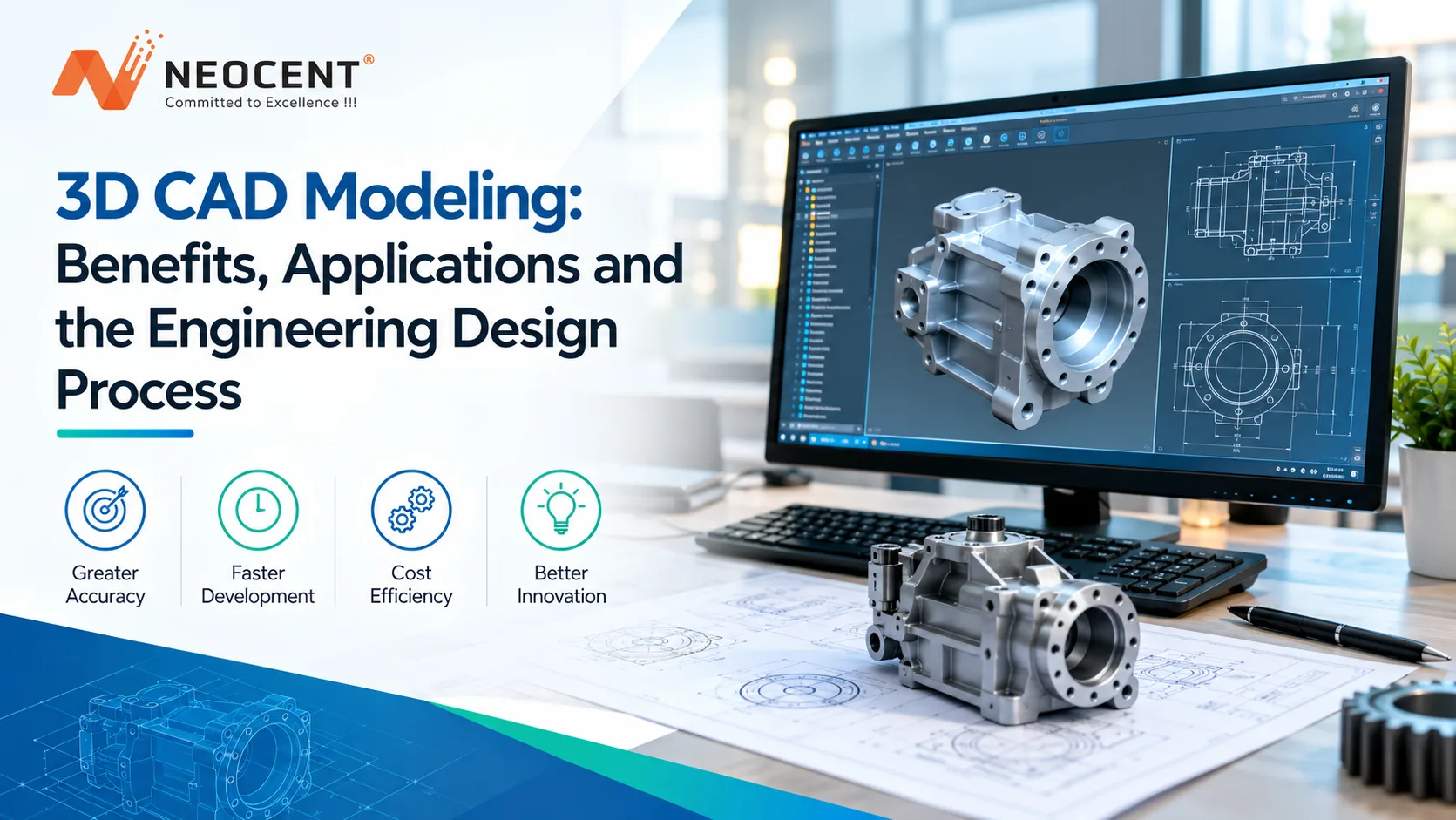
In modern engineering, accuracy, efficiency, and design coordination are essential for successful projects. 3D CAD modeling helps engineers transform concepts, technical specifications, and existing drawings into detailed three-dimensional digital models. These models make it easier to visualize components, evaluate assemblies, identify potential design conflicts, and prepare documentation for manufacturing or construction.
From industrial equipment and piping systems to structural steel and skid packages, 3D CAD modeling supports multiple stages of the engineering design process. It also helps teams communicate complex designs more clearly before physical fabrication begins.
In this guide, we explore what 3D CAD modeling is, its major benefits, industrial applications, and the steps involved in developing an accurate engineering model.
What Is 3D CAD Modeling in Engineering?
3D CAD modeling, or three-dimensional computer-aided design modeling, is the process of creating digital representations of physical objects using specialized engineering software. These models define the geometry, dimensions, features, and relationships of individual components or complete assemblies.
Unlike traditional 2D drafting, which represents objects through flat views and drawings, 3D CAD modeling allows engineers to examine a design from multiple angles and understand how different components fit together.
Depending on project requirements, a 3D model may represent a mechanical component, industrial machine, piping arrangement, structural support, or complete equipment package. Engineers can use the model to generate engineering drawings, review assembly arrangements, and support downstream analysis.
For industrial projects, 3D CAD modeling provides a practical foundation for design coordination, technical communication, and engineering documentation.
What Are the Main Benefits of 3D CAD Modeling?
Improved Design Visualization
One of the primary benefits of 3D CAD modeling is the ability to visualize engineering designs before manufacturing or installation. Engineers and project stakeholders can examine component shapes, equipment arrangements, and assembly relationships in a realistic three-dimensional environment.
This improves communication between design teams, project managers, manufacturers, and clients. Potential misunderstandings can be identified earlier, reducing the need for repeated clarification during later project stages.
Better Design Accuracy and Consistency
3D CAD software enables engineers to define dimensions, geometric features, and component relationships precisely. When models are developed using verified project information, they can help maintain consistency across assemblies and related engineering drawings.
However, model accuracy depends on the quality of the input data, design assumptions, tolerances, and verification procedures. Proper engineering reviews remain essential before models are used for manufacturing or construction.
Early Clash and Interference Detection
Industrial projects often involve multiple systems operating within limited spaces. Equipment, piping, structural members, and supports may compete for the same physical space.
A coordinated 3D model helps engineers identify potential clashes and insufficient clearances before installation. Resolving these issues during design can reduce site modifications, rework, and project delays.
More Efficient Design Revisions
Engineering projects frequently require changes due to updated specifications, equipment dimensions, client feedback, or site constraints. A well-organized 3D CAD model can make these revisions easier to manage.
Engineers can update affected components and review their relationships with the rest of the assembly. Depending on the software and modeling approach, associated drawings may also be updated from the revised model.
Improved Collaboration Between Engineering Teams
Complex projects require coordination among mechanical, piping, structural, and other engineering disciplines. Shared models and compatible data formats help teams review interfaces and understand how their designs interact.
Better coordination can improve design reviews, support clearer communication, and reduce inconsistencies between disciplines.
Support for Manufacturing and Construction
Validated 3D models can support the preparation of general arrangement drawings, fabrication drawings, assembly details, and material take-offs where required.
These deliverables help manufacturers and construction teams understand dimensions, component locations, and assembly requirements. The specific outputs depend on the project scope and client specifications.
What Are the Applications of 3D CAD Modeling?
3D CAD modeling has a wide range of applications across industrial engineering, manufacturing, and infrastructure projects.
Industrial Equipment and Mechanical Components
Engineers use 3D CAD models to develop individual components, machine assemblies, equipment housings, frames, and mechanical systems. The models help visualize component interfaces and support dimensional reviews before production.
Piping and Plant Design
In industrial facilities, 3D modeling supports pipe routing, equipment placement, support arrangements, and spatial coordination. Engineers can review access requirements, clearances, and potential conflicts between piping and surrounding structures.
The resulting models may also support the preparation of piping isometric drawings and other project documentation.
Skid Package Design and Modeling
Skid packages integrate equipment, piping, valves, instruments, and supporting structures into a compact assembly. Three-dimensional modeling helps engineers evaluate equipment positioning, connection locations, maintenance access, and overall package dimensions.
This is particularly useful when the package must fit within specific transportation, installation, or operating constraints.
Structural Steel and Support Systems
3D CAD modeling can be used for platforms, equipment supports, pipe racks, frames, and other structural arrangements. It allows engineers to examine member positioning, connection interfaces, and the relationship between structural components and installed equipment.
Structural adequacy still requires appropriate engineering calculations and analysis when applicable.
Manufacturing and Product Development
Manufacturers use CAD models to develop products, review assemblies, and prepare designs for production. Depending on the application, the models can support prototyping, machining preparation, assembly planning, and design modifications.
Plant Modifications and As-Built Modeling
Existing facilities may require upgrades, replacement equipment, or piping modifications. Engineers can develop updated models from verified drawings, measurements, scans, and site information.
Accurate existing-condition models help teams plan modifications and evaluate spatial constraints before work begins.
What Is the Engineering Design Process for 3D CAD Modeling?
A structured workflow helps ensure that a 3D CAD model meets project requirements and provides reliable engineering information.
Step 1: Requirement and Input Collection
The process begins with gathering project specifications, existing drawings, equipment data sheets, dimensions, material information, and applicable standards. Engineers clarify the modeling scope, required level of detail, software formats, and expected deliverables.
Step 2: Concept Development and Layout Planning
Engineers establish the preliminary arrangement of components, equipment, and supporting systems. They consider available space, connection points, interfaces, and project constraints before developing detailed geometry.
Step 3: 3D Part and Equipment Modeling
Individual components and assemblies are created using the approved design inputs. Dimensions, geometric features, and interfaces are defined according to project requirements and available technical information.
Step 4: Assembly and Design Coordination
The individual models are combined into a coordinated assembly. Engineers review component relationships, equipment positioning, piping routes, and structural interfaces to identify potential conflicts and improve the overall arrangement.
Step 5: Model Review and Clash Checking
The model is reviewed for dimensional consistency, clearances, accessibility, and interference between components. Identified issues are discussed with the relevant engineering teams and resolved through approved design changes.
Step 6: Drawing and Documentation Preparation
Once the model has been reviewed, engineers prepare the required deliverables. These may include general arrangement drawings, fabrication drawings, piping isometrics, detailed component drawings, and bills of materials or material take-offs.
Step 7: Revision Control and Final Handover
The final stage involves incorporating approved comments, checking deliverables, and organizing files for handover. Models and drawings are supplied in the agreed formats, with revisions managed according to project requirements.
Which Industries Use 3D CAD Modeling?
Several industries rely on 3D CAD modeling to support design development and project execution.
- Oil and gas: Equipment layouts, piping systems, process skids, and support structures.
- Petrochemical and chemical processing: Plant arrangements, equipment interfaces, and piping coordination.
- Power generation: Mechanical equipment, auxiliary systems, and structural arrangements.
- Water and wastewater treatment: Pumping systems, treatment equipment, and piping layouts.
- Industrial manufacturing: Product development, mechanical components, and assembly design.
- Engineering, procurement, and construction (EPC): Multidisciplinary coordination, design reviews, and project documentation.
The required modeling detail varies according to the application, engineering discipline, and project stage.
What Deliverables Can You Expect from 3D CAD Modeling Services?
The deliverables depend on the project scope, source information, and client requirements. Common outputs include:
- Three-dimensional component and assembly models.
- Equipment layouts and general arrangement drawings.
- Piping layouts and isometric drawings, where included in scope.
- Structural framing and support details.
- Fabrication and manufacturing drawings.
- Bills of materials (BOMs) and material take-offs (MTOs).
- Digital models for design reviews and coordination.
Before starting a project, confirm the required file formats, drawing standards, revision procedures, and level of detail with the service provider.
How Do You Choose a 3D CAD Modeling Service Provider?
Selecting an appropriate engineering partner can influence model quality, coordination, and project delivery. Consider the following factors:
- Industry experience: Look for relevant experience in industrial equipment, piping, structures, or your specific application.
- Technical accuracy: Ask about dimensional checks, design reviews, and quality-control procedures.
- Software compatibility: Confirm that the provider can deliver the required native and neutral file formats.
- Coordination capabilities: Evaluate its approach to assembly reviews, clash detection, and multidisciplinary communication.
- Documentation quality: Check whether the provider can prepare the drawings and other deliverables required for your project.
- Project communication: Ensure that revisions, milestones, responsibilities, and deliverable expectations are clearly defined.
Reviewing relevant project examples can help you assess whether a provider’s capabilities align with your engineering requirements.
Why Consider Neocent Engineering for 3D CAD Modeling?
Neocent Engineering provides engineering services for industrial projects requiring technical modeling and design support. Its 3D modeling capabilities can help clients develop digital representations of equipment, piping systems, structural elements, and industrial assemblies according to project requirements.
A coordinated modeling approach can support design visualization, identify potential spatial conflicts, and prepare engineering documentation for subsequent project stages. The required scope and deliverables should be established based on the client’s drawings, specifications, and project objectives.
Explore our 3D Modeling Services to learn more about our capabilities. If you are planning a new engineering project or need support with an existing design, contact Neocent Engineering to discuss your requirements.
Frequently Asked Questions About 3D CAD Modeling
What is 3D CAD modeling used for?
3D CAD modeling is used to create digital representations of components, equipment, structures, and assemblies. Engineers use these models for design visualization, dimensional reviews, assembly coordination, drawing preparation, and manufacturing or construction planning.
What are the main benefits of 3D CAD modeling?
The main benefits include improved visualization, more consistent design documentation, easier design revisions, earlier identification of potential clashes, and better collaboration between engineering teams. Actual project benefits depend on model quality and the effectiveness of the review process.
What is the difference between 2D drafting and 3D CAD modeling?
2D drafting represents an object through flat views and dimensions, while 3D CAD modeling represents its three-dimensional geometry. A 3D model can help engineers understand component relationships and generate relevant 2D drawings, depending on the software and project requirements.
Can 3D CAD models be used for FEA and CFD analysis?
Yes. Suitable CAD geometry can provide a starting point for finite element analysis (FEA) and computational fluid dynamics (CFD). However, the model may require simplification, geometry cleanup, meshing, appropriate boundary conditions, and engineering validation before analysis.
What information is required to start a 3D CAD modeling project?
Typical inputs include project specifications, existing drawings, dimensions, equipment data sheets, material details, and required deliverable formats. Additional measurements or site information may be necessary when existing documentation is incomplete.
How do I select the right industrial 3D CAD modeling service?
Evaluate the provider’s relevant industry experience, technical quality checks, software compatibility, coordination capabilities, documentation standards, and communication process. Ask for relevant project examples and confirm the scope and deliverables before work begins.
Conclusion
3D CAD modeling plays an important role in modern engineering by helping teams visualize designs, coordinate components, identify potential clashes, and prepare technical documentation. Its applications span industrial equipment, piping systems, skid packages, structural supports, and manufacturing.
A structured process—from gathering project requirements to final model verification—helps ensure that digital models meet their intended purpose. By selecting an experienced engineering partner and defining clear deliverables, businesses can improve design coordination and support more informed project decisions.
Need professional 3D CAD modeling support for your engineering project? Contact Neocent Engineering to discuss your requirements and explore suitable modeling solutions.

Krupal Patel
Krupal Patel is the CEO of Neocent Engineering Pvt. Ltd., Ahmedabad, specializing in advanced engineering solutions. With over 8 years of expertise in Product Design, FEA, CFD, and ASME-BPVC stress analysis, he has successfully delivered high-precision projects across pressure vessels, piping, and structural systems.